ACERALTOS 9100B Motherboard Settings and Configuration
ACER, INC.
ACERALTOS 9100B
Device Type | Mainboard |
Processor | Pentium II |
Processor Speed | 350/400MHz |
Chip Set | Intel 440BX |
Video Chip Set | Unidentified |
Maximum Onboard Memory | 512MB (EDO supported) |
Maximum Video Memory | 2MB |
Cache | 256/512KB (located on Pentium II CPU) |
BIOS | Acer |
Dimensions | 305mm x 244mm |
I/O Options | 32-bit PCI slots (5), Ethernet 10BaseT connector, floppy drive interface, IDE interface, SCSI interface, Wide Ultra SCSI interface, PS/2 mouse port, serial ports (2), VGA port, USB connectors (2), ATX power connector, CPU slot |
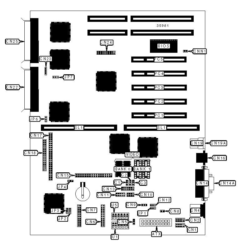
CONNECTIONS | |||
Purpose | Location | Purpose | Location |
ATX power connector | ATX | VGA port | CN14A |
Chassis fan power | C1 | IDE interface | CN15 |
Chassis fan power | C2 | Ethernet 10BaseT connector | CN16 |
Chassis fan power | C3 | SCSI interface | CN17 |
Serial port 1 | CN1 | Floppy drive interface | CN18 |
Serial port 2 | CN2 | USB connector 1 | CN19 |
PS/2 mouse port | CN4 | USB connector 2 | CN19A |
Software shutdown for 420 power | CN5 | External SCSI interface | CN22 |
RDM connector | CN6 | IDE interface LED | CN23 |
RDM connector | CN7 | SMM connector | CN24 |
Soft off power supply | CN8 | External SCSI interface | CN25 |
Software shutdown for 200 power | CN9 | Chassis intrusion connector | CNN1 |
Power LED & keylock | CN10 | 32-bit PCI slots | PC1 - PC5 |
Redundant power supply connector | CN11 | CPU slot | SL2 |
NMI signal connector | CN12 | 3.3v power | U1 |
LED connector | CN13 | 3.3v power | U5 |
Parallel port | CN14 | ||
USER CONFIGURABLE SETTINGS | |||
Function | Label | Position | |
» | Factory configured - do not alter | JP1 | Pins 1 & 2 closed |
» | Factory configured - do not alter | JP2 | Pins 1 & 2 closed |
» | Password disabled | JP3 | Pins 2 & 3 closed |
| Password enabled | JP3 | Pins 1 & 2 closed |
» | 5v standby enabled | JP4 | Pins 1 & 2 closed |
| 5v standby disabled | JP4 | Pins 2 & 3 closed |
» | On board video enabled | JP7 | Pins 1 & 2 closed |
| On board video disabled | JP7 | Pins 2 & 3 closed |
VIDEO MEMORY CONFIGURATION | ||
Size | Bank 0 | Bank 1 |
1MB | (2) 256K x 16 | None |
2MB | (2) 256K x 16 | (2) 256K x 16 |
SCSI TERMINATON SELECTION | |
Setting | JP6 |
Termination enabled | Pins 1 & 2 closed |
» Termination switchable through SCSI select utility | Pins 2 & 3 closed |
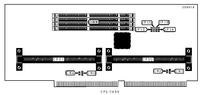
CONNECTIONS | |||
Purpose | Location | Purpose | Location |
CPU2 fan power | CN1 | CPU1 fan power | CN3 |
Thermal detection connector 2 | CN2 | Thermal detection connector 1 | CN4 |
DIMM CONFIGURATION | ||||
Size | Bank 0 | Bank 1 | Bank 2 | Bank 3 |
8MB | (1) 1M x 64 | None | None | None |
16MB | (1) 2M x 64 | None | None | None |
16MB | (1) 1M x 64 | (1) 1M x 64 | None | None |
24MB | (1) 2M x 64 | (1) 1M x 64 | None | None |
24MB | (1) 1M x 64 | (1) 1M x 64 | (1) 1M x 64 | None |
32MB | (1) 4M x 64 | None | None | None |
32MB | (1) 2M x 64 | (1) 2M x 64 | None | None |
32MB | (1) 1M x 64 | (1) 1M x 64 | (1) 1M x 64 | (1) 1M x 64 |
40MB | (1) 4M x 64 | (1) 1M x 64 | None | None |
48MB | (1) 4M x 64 | (1) 2M x 64 | None | None |
48MB | (1) 2M x 64 | (1) 2M x 64 | (1) 2M x 64 | None |
64MB | (1) 2M x 64 | (1) 2M x 64 | (1) 2M x 64 | (1) 2M x 64 |
64MB | (1) 8M x 64 | None | None | None |
64MB | (1) 4M x 64 | (1) 4M x 64 | None | None |
72MB | (1) 8M x 64 | (1) 1M x 64 | None | None |
80MB | (1) 8M x 64 | (1) 2M x 64 | None | None |
96MB | (1) 8M x 64 | (1) 4M x 64 | None | None |
96MB | (1) 4M x 64 | (1) 4M x 64 | (1) 4M x 64 | None |
DIMM CONFIGURATION (CON'T) | ||||
Size | Bank 0 | Bank 1 | Bank 2 | Bank 3 |
128MB | (1) 16M x 64 | None | None | None |
128MB | (1) 8M x 64 | (1) 8M x 64 | None | None |
128MB | (1) 4M x 64 | (1) 4M x 64 | (1) 4M x 64 | (1) 4M x 64 |
136MB | (1) 16M x 64 | (1) 1M x 64 | None | None |
144MB | (1) 16M x 64 | (1) 2M x 64 | None | None |
176MB | (1) 16M x 64 | (1) 2M x 64 | (1) 2M x 64 | (1) 2M x 64 |
192MB | (1) 16M x 64 | (1) 8M x 64 | None | None |
192MB | (1) 8M x 64 | (1) 8M x 64 | (1) 8M x 64 | None |
256MB | (1) 16M x 64 | (1) 16M x 64 | None | None |
256MB | (1) 8M x 64 | (1) 8M x 64 | (1) 8M x 64 | (1) 8M x 64 |
272MB | (1) 16M x 64 | (1) 16M x 64 | (1) 1M x 64 | (1) 1M x 64 |
288MB | (1) 16M x 64 | (1) 16M x 64 | (1) 2M x 64 | (1) 2M x 64 |
320MB | (1) 16M x 64 | (1) 16M x 64 | (1) 4M x 64 | (1) 4M x 64 |
384MB | (1) 16M x 64 | (1) 16M x 64 | (1) 16M x 64 | None |
512MB | (1) 16M x 64 | (1) 16M x 64 | (1) 16M x 64 | (1) 16M x 64 |
Note: Board accepts EDO memory. | ||||
CACHE CONFIGURATION |
Note: 256KB/512KB cache is located on the Pentium II CPU. |
CPU SPEED SELECTION | ||||||
CPU speed | Clock speed | Multiplier | JP1A | JP1B | JP1C | JP1D |
350MHz | 100MHz | 3.5x | 1 & 2 | 2 & 3 | 2 & 3 | 1 & 2 |
400MHz | 100MHz | 4x | 1 & 2 | 1 & 2 | 1 & 2 | 2 & 3 |
Note: Pins designated should be in the closed position. | ||||||


My Books